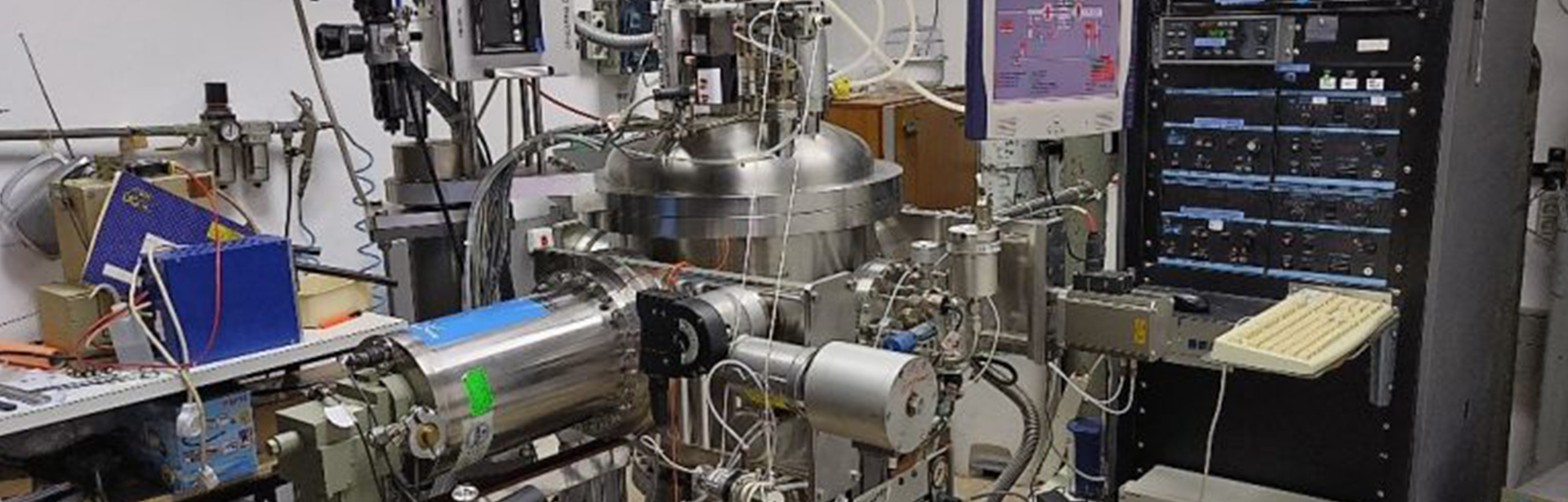
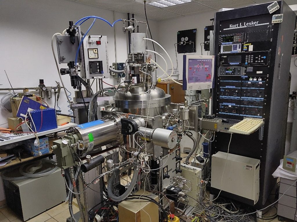
The sputtering system in our lab for thin films coatings
A Schematic illustration of the experimental set-up for the electrochemical anodization of Al substrate to form a porous alumina layer. a) The structure of the sample holder. b) The sample geometry inside the preparation vessel.
Characterization Equipment
Dielectric properties
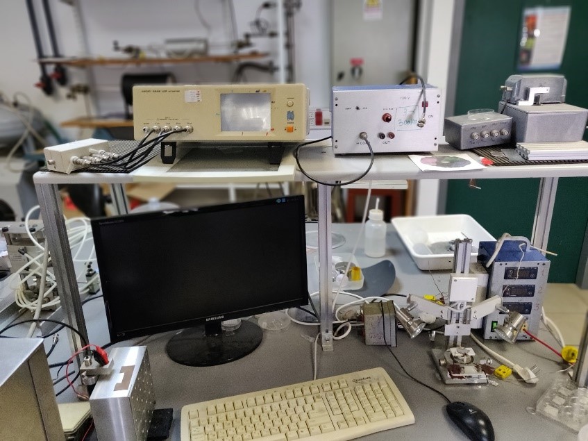
The dielectric measurements are performed with the LCR Hioki impedance analyzer. It enables measurements of dielectric capacitance, conductance and impedance at frequencies between 100Hz and 4MHz under applied electric voltage up to 30V. The measurements can be done at room temperature or during heating at temperatures up to 1200C. The measurement system is computerized and operated by a labview program.
The dielectric measurements system.The piezoelectric measurements system.
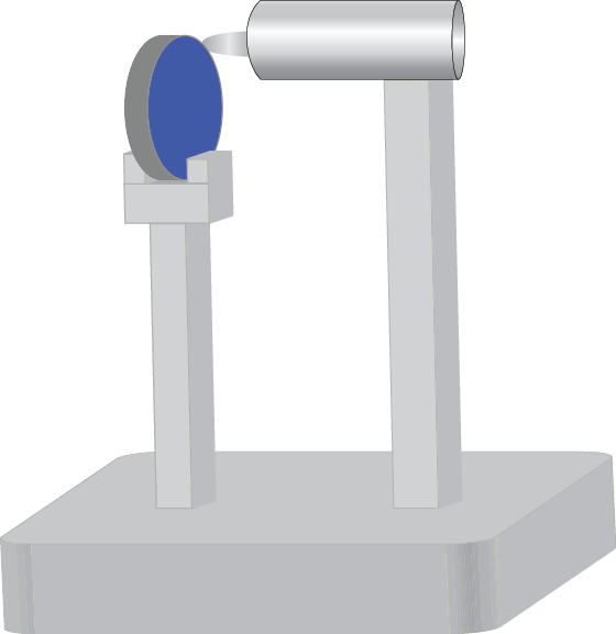
A schematic illustration of the cantilever bending technique for measuring a piezoelectric response.
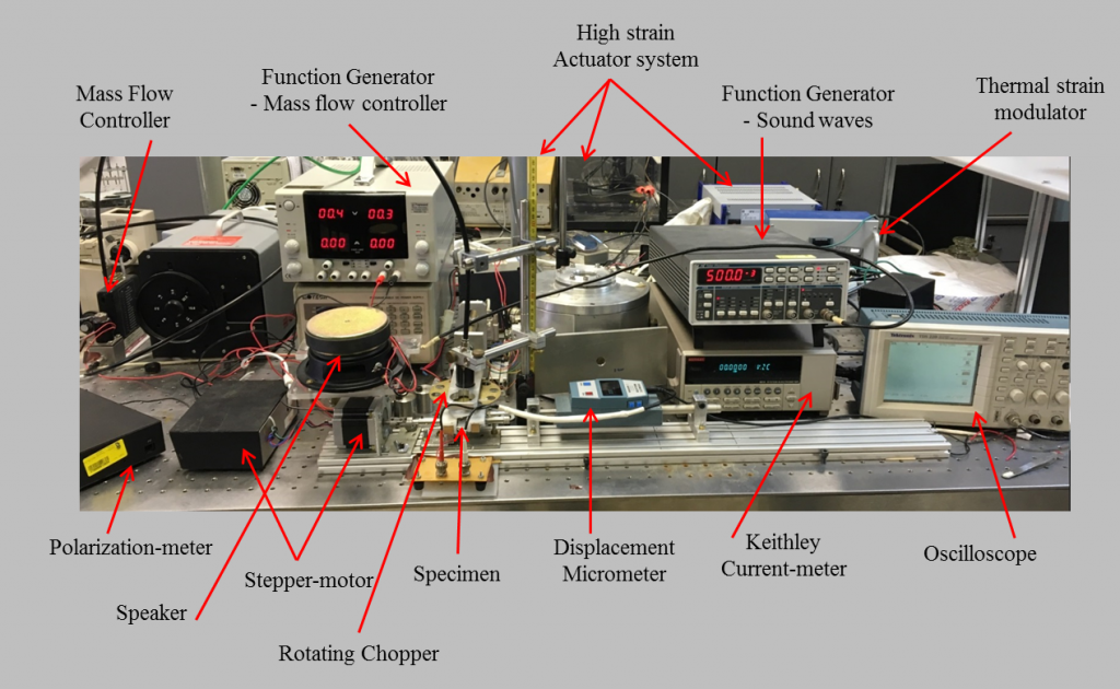
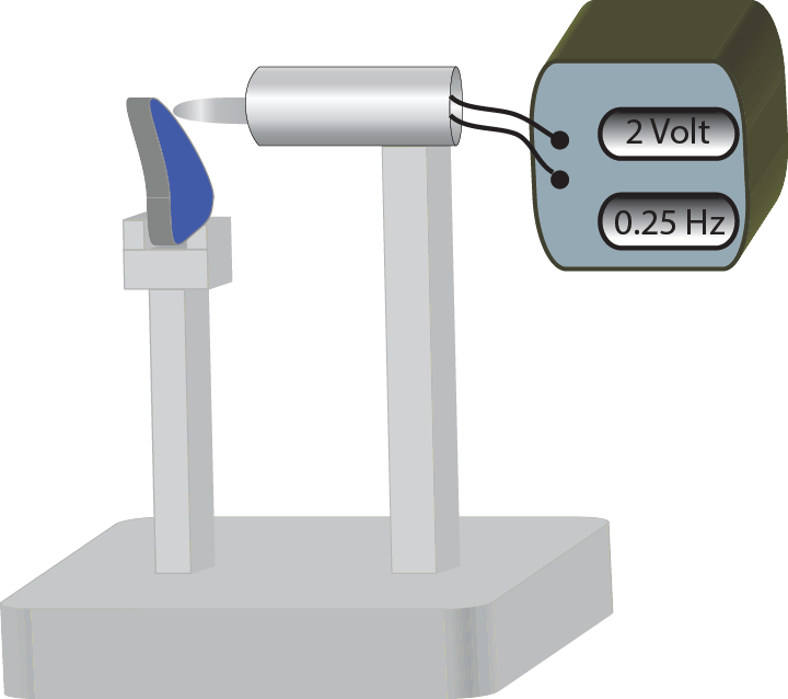
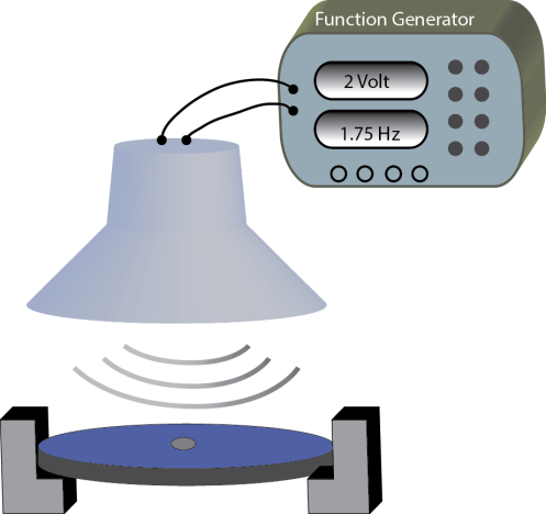
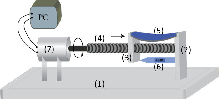
A schematic Illustration of the system that generates ultra-low mechanical pressure by an air flow. The sample is clamped at two opposite ends; its center is exposed to an air flow from a needle. The amplitude of the air flow is controlled by a mass flow controller. The time modulation of the applied mechanical pressure is made by a periodic chopping of the air flow by a rotating wheel with holes.A schematic Illustration of the system that generates ultra-low applied mechanical pressure by soundwaves. The sample is clamped at two opposite ends; its center is exposed to soundwaves generated by a loud speaker, which is driven by a square shaped voltage from a function generator.A schematic illustration of the system used for inducing a static strain by bending the sample. It consists of (1) track, (2) fixed holder, (3) movable holder, (4) screw, (5) samples, (6) micrometer and (7) stepper-motor.A schematic illustration of piezoelectric measurements system. A mechanical pressure is applied on the sample; the consequent piezoelectric current response is measured by a current-meter connected to an oscilloscope.